Time for an update on the ZX81 project!
TL;DR it works, with just a few hiccups during bring-up.
The board was populated with new 74HC logic chips, and with nice turned pin IC sockets for the Z80, ROM and RAM. For CPU and RAM, I already had a stash of old chips, which I used. For ROM, I used a SST NOR Flash, which I programmed with a TL866ii.

The first issue I ran into when trying to boot the board, was that it didn’t reset reliably on power on. It turns out that the capacitance in the RC network was too small (100 nF), so the reset pulse was not long enough for the board to initialize. The reset button worked fine, however. Replacing the capacitor with a 1 uF electrolyte solved that issue.
The second issue was related to the RAM. I had installed a brand new 28 pin RAM in my 28/32 pin socket, and while it was clear that the CPU did something, it clearly crashed during boot. After scratching my head a bit, I realized that the high-order address bits were incorrectly wired to the RAM. In the case of a 28 pin RAM, one of the high address bits on the board would map to CE2, but remain low, so the RAM would effectively not work. This could easily be patched with a wire bodge on the RAM chip.

Above is the first output from the ZX81, on a bare CRT. I have no keyboard at this point, so the text on the screen is the result of just connecting a few pins on the keyboard connector.
Next steps: Keyboard
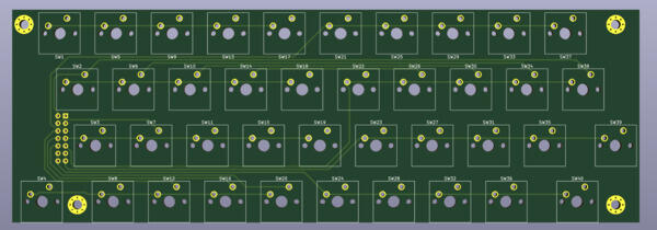
To be able to control the computer, I’ll need a keyboard. I opted for designing a PCB for a keyboard with mechanical switches instead of the typical Sinclair membrane keyboard. Below is a render of the 40 key Cherry MX-compatible PCB. I figure I’ll print a base with a FDM printer, and make a top lid in PMMA/Plexiglas using the laser cutter at the local makerspace.

Display
For the display part, I’m planning on using the 5” black-and-white CRT pictured above. The CRT and the driver board comes from a cheap Chinese TV I bought ages ago, when playing around with microcontroller generated video.
I’m planning on making a new, neater circuit board, and move the exotic components there (flyback transformer, KA2915 TV-on-a-chip). Much of the original board area is spent on the RF frontend, audio and video IF processing, and audio amplifier. Getting rid of that, in combination with the switch to a two-layer board, should allow a much smaller and neater PCB.

I’ll write a separate post on the CRT design and share the design files as I wrap it up. The main remaining work is replicating the footprint of the FBT (no datasheet can be found), and figure out some transistor part numbers.
To be continued :)